![]()
Infrared (IR) communication is a widely used communication technology. A typical example for IR communication is a TV remote control that sends IR signals to a TV. In particular, the remote’s IR light is repeatedly switched on and off (typically 38kHz / 38.000 times per second). The advantages of IR technology are it’s inexpensive and undetectable to the human eye. The disadvantage is that the IR light must be directed towards the IR receiver. As a consequence, IR communication should not be applied if sender and receiver are in different rooms (Bluetooth or WiFi might be a better choice then).
This tutorial gives an introduction to the “IR transmitter” and “IR receiver” modules. My pairs of IR transmitter and receiver are no-name products. Often, you find these products also under different names (e.g. IR emitter, IR sender) or with a version number as postfix (e.g. V1.0). The good news is that they are built up very much alike. Therefore, this tutorial should also work for similar products (HX-M121, HX-53, KY-005, KY-022, YL-55) from other manufacturers and vendors (Keyes, Iduino, Open Smart,…).
![]()
The IR transmitter module has an IR LED to send signals. Normally, the LED operates around 940nm, i.e. the LED is very bright in the IR spectrum. Besides the LED, the module has three pins to power and control the module: GND, VCC, and DAT. And that’s about basically everything that is needed to send signals over IR communication. In fact, this is the reason why IR communication is so cheap. You need only an (IR) LED to get started.
The pins GND and VCC are for powering the module with a 5V power supply (e.g. Arduino GND and 5V pin header). The DAT pin corresponds to the data signal that should be sent to an IR receiver. If you have another type of IR sender, the SIG pin might have a different name. For example, S for Iduino module and KY-005,…
IR receiver modules have typically an integrated IR receiver unit, such as the TSOP382, TSSP4P38 etc. These units have already everything included that is needed to sense an IR signal (PIN diode, bandpass, demodulator,…).
The pin layout is very similar to the IR transmitter. There is a GND and VCC pin to power the module with a 5V voltage supply. The received IR data can be read from the DAT pin. The pin layout is basically also the same for other IR receiver modules. The DAT pin has often a different name. For example, S for KY-022, DO for YL-55,…
There exist different protocols that define how a signal/message is sent from an IR transmitter to an IR receiver. The use of different protocols are, e.g., one reason why a remote control of a TV does often not work for with another TV. This tutorial does not dive deeper into the topic of IR protocols. Nonetheless, it’s already good to know that there exist different protocols (NEC, JVC, Samsung,…) for IR communication.
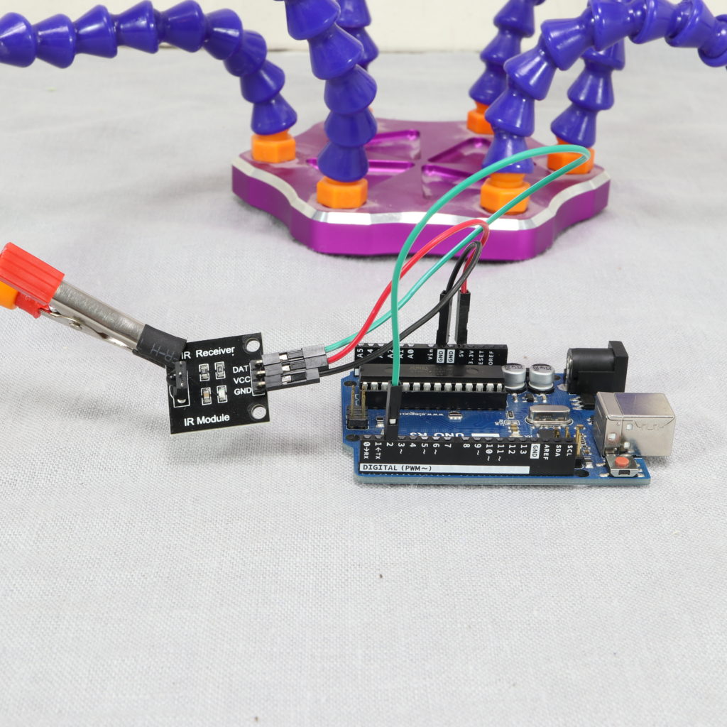
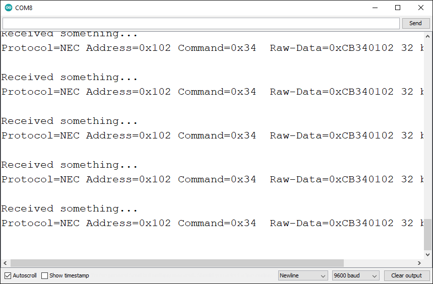
The idea of the example application is to have an IR receiver and IR transmitter module. Each module is controlled by an Arduino Uno (=two different Arduinos are used). The sending Arduino Uno uses the “NEC protocol” to send a message with the IR transmitter module. The receiving Arduino Uno uses the IR receiver module to receive the message and then prints out the message’s content.
The wiring for powering is the same for both pairs of Arduinos and modules. Both modules have an operating voltage of 5V. For each module, use a jumper wire and connect the Arduino’s GND pin to the module’s GND pin. Do the same for each module to connect the Arduino’s 5V pin to the module’s VCC pin.
For the sending Arduino Uno, wire the Arduino’s pin 3 to the module’s DAT pin.
![]()
![]()
The IR transmitter and IR receiver modules are very useful when someone wants to get started with IR communication. These cheap modules work very well for a wide range of applications and are very simple to use. If you plan to use them under difficult conditions (shining sunlight, no direct line of sight,…), I recommend to evaluate first, whether these cheap modules fit to your requirements. The good news is, “more expensive / better” IR modules work in the same way as presented here.
Previous article Next article
Hey there was trying to use this but it says that IrSender.begin(PIN_SEND); // Initializes IR sender is too ambiguous?
Im new to Arduino so I don’t quite understand.
thanks
I had a similar error, fix was an update to IRremote, it was drawing from 2.x instead of 3.x which changes some stuff
>>>Initializes IR sender is too ambiguous? The same issue.If you get the “sender is too ambiguous” error, replace:
IrSender.begin(PIN_SEND); with:
IrSender.begin(PIN_SEND, ENABLE_LED_FEEDBACK);
Hello there. I hope you’re well. I am looking to use a pair of the HX-M121 sensors to make a simple light beam gate. When an object crosses the beam, I want to know. I can not find any examples for this application. Do you know of any? Thanks.
Hi, excellent article, im bad in electronics, just learning, im trying to upgrade to put 4 ir leds to control some electronics, but i dont know wich capacitor i hace to use and wich resistence at the base of the transistor, could you give me a hand? i find lots examples of leds and transistors but when i tried it doesn´t work.
thanks at all
Erica
Im attemping this lab for a project for my son and it doesnt work says the following. C:\AppData\Local\Temp\.arduinoIDE-unsaved2023424-6748-7mavc0.uzg03\sketch_may24a\sketch_may24a.ino: In function ‘void setup()’:
C:\AppData\Local\Temp\.arduinoIDE-unsaved2023424-6748-7mavc0.uzg03\sketch_may24a\sketch_may24a.ino:9:3: error: expected initializer before ‘IrSender’
IrSender.begin(PIN_SEND); // Initializes IR sender
^~~~~~~~
C:\AppData\Local\Temp\.arduinoIDE-unsaved2023424-6748-7mavc0.uzg03\sketch_may24a\sketch_may24a.ino: In function ‘void loop()’:
C:\AppData\Local\Temp\.arduinoIDE-unsaved2023424-6748-7mavc0.uzg03\sketch_may24a\sketch_may24a.ino:14:41: error: no matching function for call to ‘IRsend::sendNEC(int, int, bool, int)’
IrSender.sendNEC(0x0102, 0x34, true, 0); // the address 0x0102 with the command 0x34 is sent
^
In file included from \\Arduino\libraries\IRremote\src/IRremote.hpp:308:0,
from \\Arduino\libraries\IRremote\src/IRremote.h:10,
from C:\AppData\Local\Temp\.arduinoIDE-unsaved2023424-6748-7mavc0.uzg03\sketch_may24a\sketch_may24a.ino:1:
\\Arduino\libraries\IRremote\src/ir_NEC.hpp:173:6: note: candidate: void IRsend::sendNEC(uint16_t, uint8_t, int_fast8_t)
void IRsend::sendNEC(uint16_t aAddress, uint8_t aCommand, int_fast8_t aNumberOfRepeats) ^~~~~~
\\Arduino\libraries\IRremote\src/ir_NEC.hpp:173:6: note: candidate expects 3 arguments, 4 provided
In file included from \\Arduino\libraries\IRremote\src/IRremote.hpp:266:0,
from \\Arduino\libraries\IRremote\src/IRremote.h:10,
from C:\AppData\Local\Temp\.arduinoIDE-unsaved2023424-6748-7mavc0.uzg03\sketch_may24a\sketch_may24a.ino:1:
\Arduino\libraries\IRremote\src/IRremoteInt.h:572:10: note: candidate: void IRsend::sendNEC(uint32_t, uint8_t)
void sendNEC(uint32_t aRawData,
^~~~~~~
\Arduino\libraries\IRremote\src/IRremoteInt.h:572:10: note: candidate expects 2 arguments, 4 provided exit status 1 Compilation error: expected initializer before ‘IrSender’ I have the code which I copied and pasted exactly as you posted. I only changed the input pin to A0 and the beacon output to 12. If you could help me I could greatly appreciate it.